
Great job Dick, very nicely done.
Mike


 Junior Member
Great job Dick, very nicely done.
Mike
All Gave Some,
Some Gave All.
My computer configuration and software used:
Gigabyte GA-990XA-UD3 Motherboard, AMD FX 6-core Processor Black Edition, 32 Gig DDR 3 Ram, Gigabyte HD 6450 Video Card with 1 Gig DDR 3 ram, Windows 10
Designer 2.007, Designer 3.102, Pattern Editor, Centerline, Conforming Vectors, 2d Tools, 3d Tools, DXF Importer, STL Importer and Rotary Jig.
 Senior Member
Thanks.
Before I developed the microcontroller circuit that I use in my own clock designs, I had developed a more robust (than other published circuits) op amp circuit for electromagnetic pendulums. Other clock builders have contacted me and purchased electronics kits to drive their clocks. A number of builders of Clayton Boyer's Toucan clock have done so. Last March, Rolf Beuttenmuller used my circuit to drive a clock that he built which was designed by Alfred Mifsud. The plans for this clock were recently published in a special Scroll Saw Woodorking and Crafts magazine edition Gizmos and Gadgets, and I am listed as a source of electronics: http://www.scrollsawer.com/2015/10/0...-gadgets-2015/ So in addition to making sawdust, I have a mini electronics production line going.
Mr. Mifsud's design is a clever simplification that basically uses no gears. I may have to steal it for a future clock project.
 Senior Member
Sweet. I just picked up the mag last week and couldn't figure out where to get the electronics.
Congrats by the way.
Senior Member
Back to the original project.
Senior Member
That is really cool in a nerdy kind of way. Great looking project though.
Senior Member
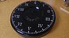
Here is the finished clock:
This unique clock also has a unique mechanism. I used three stepper motors, one for each hand, rather than one motor and lots of gears. Here you can see the three motors with their driving gears. The hours shaft with its driven gear has been inserted and meshes with the hours motor.
Here the minutes and seconds shafts have been inserted.
The motors are driven by the driver boards that came with them. These are controlled by a TI MSP430 microcontroller. I programmed the microcontroller to step each motor at the proper speed to make a metric clock. A pushbutton switch allows a person to align the hands, set the current time, and start the clock.
The red board is actually a development board called Launchpad. It is typically used for development only. Often the complete project has many more components, so a unique circuit board is designed to hold only the microcontroller and the other added components, eliminating the development tools hardware. In this case, other than the driver boards, there are only two other components. The Launchpad is inexpensive - it would have cost me considerably more to get a custom circuit board made. And, this is really a prototype. So, in this case, I just used the Launchpad. If I build more (it appears there may be a market, as true metric clocks are scarce) I will design a custom board.
The Launchpad is USB powered (the cable is not shown in the photo, but you can perhaps spot the mini USB port on the red board). The motor drivers require 5 v power, which I stole from a convenient test point on the Launchpad.
Last edited by DickB; 11-24-2015 at 09:26 AM.
 Senior Member
That is very cool. Nice solution. I imagined it would have had to be much more complicated. How well will it keep time?
Senior Member
It uses the same watch crystal timebase as my pendulum clocks, as do most watches and clocks for that matter. Typical specs are 10 ppm (parts per million), so worst case about a second per day. Some crystals operate very close to spec. This one is within a second after 5 metric hours (so how many standard hours is that?). We'll see after a day or two.
You might enjoy the math needed to figure out how to time each step of each motor. Watch crystals are miniature tuning forks set to a frequency of 32768 Hz, which is a power of two. Microcontrollers use binary arithmetic, so it is straightforward to derive a 1-second timebase or "tick" from a watch crystal timebase. Metric seconds are .864 standard seconds, so the nice binary arithmetic goes out the window. Also, the stepper motors have 32 steps per revolution with an internal gear train often stated as a 1:64 ratio, but actually the ratio is slightly less at 1:63.68395. So some floating point math in the microcontroller is required.
While developing the code, I first used the parameters for a standard clock, because it was difficult getting my head around the whole metric deal. It was easier for me to confirm the hands were moving in proportion as they should. I made up some paper standard clock faces to assist. Once I got the standard clock working, I plugged in the metric constants and it worked.
So actually what I have is a fully programmable clock. Want 24 hours per revolution rather than 12? No problem. Want it to run backwards? No problem. Want the second hand to jump in intervals rather than continuous? No problem.
Actually, what might be cool is a clock with both metric and standard markings, and hands that alternate between metric and standard time every 15 seconds or so. Hmmm...
Last edited by DickB; 11-24-2015 at 09:38 AM.
Banned
I still cannot grasp how to tell what time it is? LOL We would need a lcd screen interpreter clock to go with it.
Senior Member
Ha! You read it like a standard clock, so in the photo it is 3:19:60. 10:00:00 is midnight, and 5:00:00 is noon. So hour three is more than halfway between midnight noon, or somewhere in the 7-8 am vicinity.Originally Posted by normrichards

Here is one dual clock that may help: http://www.metricclock.com/
Last edited by DickB; 11-24-2015 at 11:41 AM.
 Posting Permissions

 Reply With Quote