
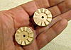
Designed and cut this clutch assembly, to allow the time to be set by moving the minute hand clockwise. A light spring or a weighted lever should hold the clutch while operating.


 Senior Member
Designed and cut this clutch assembly, to allow the time to be set by moving the minute hand clockwise. A light spring or a weighted lever should hold the clutch while operating.
Senior Member
Well, I had one of those d'uh moments about 10 seconds after I installed that clutch. I made it with 12 teeth for no reason except the size of the thing seemed right, then realized that with it I could only set the time in 5-minute intervals. Back to the drawing board. The new clutch works well. I had intended to set the time by manually moving the minute hand, but it's easier to grab the driven part of the clutch and turn it like a knob. I may make this more knob-like in the future.
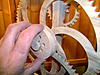
I tweaked the electronics and got the pulse width down sufficiently that I believe it will run for a year on D cells. I only have AA cells and battery holder, so am using them for now. The clock makes a little more noise than I would like. I already made one small modification to quiet it and I have a couple more ideas. I'm running tests to ensure that the pendulum length is sufficient to be able to make the proper speed adjustments. The lower rod will be replaced with brass threaded rod and a couple knurled nuts to facilitate this. Other than that, this prototype is close to finished.
I have to say myself it is cool to see this running with no visible means of motivation. The owner of a consignment shop I sell in came over, and I showed him the clock - he had not seen or heard of it before. He really liked it. I asked him if he knew what kept it going, and he said that he had no idea.


 Senior Member
Dick... Wooden gear clocks have always fascinated me and I have enjoyed following your progress as you develop such an interesting clock.
 Senior Member
Very cool! One of the neatest things I have seen done on the CarveWright!
Happy carving , Jeff Birt
Check out www.soigeneris.com for CarveWright Accesories.
Home of the 'Carving in the Dark' back lit LCD kit!
Senior Member
Not much of a mystery if you've been following this thread. I switched to a better and quieter pawl drive mechanism. The clock is running within one minute per day, and with the pendulum weight adjusting mechanism I can now easily tweak that for better accuracy. I will need to run the clock for a few weeks to better determine accuracy. I did make one or two small improvements making it a bit easier to build, which I'm testing out on my second clock build underway now, but other than that the design is finalized. I believe the design is quite robust and forgiving for beginners, because the pendulum drive appears to have enough power to overcome less-than-perfect parts and assembly.
Banned
I am really looking forward to building this clock someday! Great Job.
Senior Member
Dick... does this mean that the project will some day show up in the pattern store?
Senior Member
I'm headed in that direction.Originally Posted by SharonB

I'm also working on supplying a kit of hardware parts. Although the circuit board is not that difficult to build for an electronics hobbyist, many CarveWright owners are not familiar with electronics. So I think it would be wise to have a kit with a built and tested circuit board, battery holder, and coil available. Likewise, a number of specialty parts - miniature ball bearings, threaded brass rod, brass knurled nuts, rare earth magnet, etc. - are needed. These can all be obtained through internet suppliers, but they are somewhat expensive in small quantities due to shipping. So again, having a kit of these parts available from a single source would make it more convenient and less expensive to build this project.
 Member
Excellent, even though I have experience building this type of electronics I would still prefer a kit due to the very reason you just mentioned. If you need a beta tester for the project when it is nearing readiness I would like to volunteer.
dave
Senior Member
I just got my first batch of circuit boards in this morning. I built one up to check out, and it's running my second clock. I'm able to finish up photos for the build instructions. I hope to have this project available within a few weeks.

 Posting Permissions

 Reply With Quote