-

And here is what they would look like when taking the same profile in Moi and making it into a 3d pattern.
As I said these are not finished, I plan on sculpting the knight to give it a horse feature, then doing the UV maping again to see how that goes.
Using Designer 1.187, STL importer, Center line, conforming vectors, scanning probe/PE, and the ROCK chuck.
Eddie
-
Very interesting. So far, I can only unwrap patterns that I can describe mathematically. Given a surface in terms of two variables (u,v), I convert to cylindrical coordinates and unwrap. By U V mapping, are you referring to the method 3d programs use to map textures to surfaces? I wonder if there are any 3d programs which given a surface and an axle, will unwrap. An open source program where we could write our own routine?
This is a great source of interesting problems. For example, is it possible to carve past center and what would such a pattern look like?
-
Bergerud, you have it right, there are a few methods of UV mapping, cylinder is one, Ball shape, shrink wrap to mention a few. I am not that versed in them but know of their existence. As for programs, I hear artcam can unwrap a 3d model, and blinder (a free 3d software) has uv mapping, baking, displacement, normal, specular mapping, all of which come into play. I have Silo, and ZB along with MoI3d. Silo and ZB also have the ability. So I would say it is along the same line as what you are doing.
U and V are the X and Y coridance.
Last edited by eelamb; 01-30-2012 at 10:36 AM.
Using Designer 1.187, STL importer, Center line, conforming vectors, scanning probe/PE, and the ROCK chuck.
Eddie
-
Example of the loft command in Moi3d. Take 2 profiles, and space them a set distance, then loft the profile between the two. This is fine for anything that would be similar to an item turned on a lathe.
Edit: this profile (single line) when revolved along the axis, become the pawn as shown below.
Last edited by eelamb; 01-30-2012 at 10:59 AM.
Using Designer 1.187, STL importer, Center line, conforming vectors, scanning probe/PE, and the ROCK chuck.
Eddie
-
Bergerud - Check out blender. Here is some info on unwrapping the uv map http://wiki.blender.org/index.php/Do.../UV/Unwrapping there are also a ton of free tutorials on blender and uv mapping.
Eddie - Funny how you brought up the UV mapping. I never had a desire to get into texturing etc in modeling until a few months ago. I got into doing some stuff with 3d content and flash. I needed smaller file sizes so UV mapping and normal maps, displacement maps, color maps, speculars maps..etc. The UV map with baked displacement, flattened, then put on a plane, then export as stl to cw, should work no problem.
-
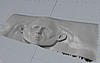
this a rough shot at it but it should work..lol eventually..more tweaking to do...quick try in zbrush with uvmaster..uv master not the best for laying uv's out but it was fast...played around with the demo head, created displacement map, tweaked map ( picture has teeth an eyes..I didnt seperate) moved to plane, kept poly's low to test bent 360...with some more tweaking this should work. Definte mind teaser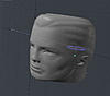

-
Ok taking a primitive head (provided in Silo), here is what I got from it. Now I need that bottle of scotch John keeps talking about to clear my head
Using Designer 1.187, STL importer, Center line, conforming vectors, scanning probe/PE, and the ROCK chuck.
Eddie
-
That does look promising. Can the displacement map be converted to gray scale ?
-
Bergerud
A displacement map, unlike a normal map, will affect the actual geometry. So the flow would go like this - Make the model in full 3d, then create uv layout, then bake displacement map to uv layout, then take a plane and place displacement map and convert to either stl or heightmap from there. The tricky part is getting the uv lay right - ie the seam and also getting the sizing correct.
Eddie..LOL scotch doesnt help on this one...LOL
-
Here is an article on displacement maps in Zbrush.
http://www.pixologic.com/docs/index....placement_Maps
Just one of the many pages on the web dealing with this subject.
added blender instructions. http://wiki.blender.org/index.php/Do...ump_and_Normal
Last edited by eelamb; 01-30-2012 at 04:43 PM.
Using Designer 1.187, STL importer, Center line, conforming vectors, scanning probe/PE, and the ROCK chuck.
Eddie
 Posting Permissions
- You may not post new threads
- You may not post replies
- You may not post attachments
- You may not edit your posts
-
Forum Rules


 Reply With Quote
